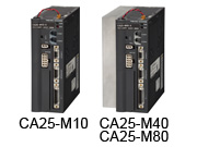
BA-Ⅲ Controller (Master Unit)
Master Unit 【CA25-M10,M40,M80】
Overview

* This is used as a master unit for control of single-axis models to four-axis models. It includes a driver board for a single axis.
* Programs use the same COMPO ARM language as before for enabling easy teaching operations.
* The power supply uses multi-power (100 V to 115 V AC, 200 V to 230 V) for supporting globalized production.
* The input signal can be selected from NPN type or PNP type.
* In sequential mode, a multitask function (number of controlled axes: 4) capable of handling up to four tasks is provided for enabling the simultaneous execution of multiple jobs.
Specifications
| Controller model | CA25-M10 | CA25-M40 *1 | CA25-M80 *2 | ||
|---|---|---|---|---|---|
| Number of controlled axes | 1-axis control or simultaneous 2-axis control by connecting a slave unit. | ||||
| Motor capacity *3 | 50 | 100 | 200 | 400 | 750 |
| Drive system | AC servo motor | ||||
| Control system | PTP, CP, semi-closed loop control | ||||
| Teaching method | Remote teaching, direct teaching or MDI | ||||
| Speed setting | 10 steps (variable) | ||||
| Acceleration setting | 20 steps (variable) | ||||
| Operation mode | Sequential, palletizing, external point designation | ||||
| Operation method | Step, continuous, single | ||||
| CPU | 32-bit RISC CPU | ||||
| Home position sensor input | Included | ||||
| Regenerative function | Included (ABSU-2000 installed) |
Included (ABSU-4000 installed) |
Included (ABSU-8000 installed) |
||
| Dynamic brake function | Not included | ||||
| Self-diagnosis function | CPU error, memory error, driver error, power supply voltage error,program error, or other error by watchdog timers | ||||
| Number of programs | Sequential: 16, Palletizing: 16 | ||||
| Number of program steps | Max. 2,500 steps + Coordinate table: 999 (Total number of all tasks) | ||||
| Memory system | FRAM | ||||
| Number of counters | 99 | ||||
| Number of timers | 9 | ||||
| Error display | Error indicator lamp turns on (front panel), teach pendant | ||||
| External input | System input: 4 inputs, general-purpose input: 4 inputs * 4 | ||||
| External output | System output: 4 outputs, general-purpose output: 4 outputs * 4 | ||||
| Communication function | For teach pendant or for PC communication × 1 channel (RS-232C) | ||||
| Power supply | 100 V to 115 V AC, 200 V to 230 V AC, ±10% 50/60 Hz(Switching between 100 V system and 200 V system by the short bar on VOLTAGE SELECT terminal on terminal block) | 200 V to 230 V AC ±10% 50/60 Hz | |||
| Power capacity (per axis) |
140VA | 210VA | 600VA | 1.2kVA | 1.6kVA |
| Operating temperature range | 0°C to 40°C | ||||
| Operating humidity range | 30% to 90% RH (no condensation) | ||||
| Storage temperature range | -20°C to 70°C | ||||
| Storage humidity range | 30% to 90% RH (no condensation) | ||||
| Environment | Indoor (not exposed to direct sunlight), 1000 m or less above sea level Location not exposed to dust, dirt, corrosive gases, or flammable gases |
||||
| Vibrations | 9.8 m/s^2 or less | ||||
| Dimensions | 55 (W) × 160 (H) × 150 (D) (Not including mounting fixtures) |
85 (W) × 160 (H) × 150 (D) (Not including mounting fixtures) |
|||
| Mass (kg) | 0.92 | 1.58 | |||
*1: When using the CA25-M40, be sure to use the regenerative discharge unit ABSU-4000.
*2: When using the CA25-M80, be sure to use the regenerative discharge unit ABSU-8000.
*3: Identify the applicable motor capacity using the naming format on the controller front panel.
Do not connect to a motor with a different capacity. This can lead to motor burn out or other damage.
*4: General-purpose I/O can be used as an I/O signal for various system types based on the mode settings.
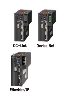
Master Unit 【CA25-M10,M40,M80】 CC-Link Unit, DeviceNet Unit,EtherNet/IP Unit
Overview

This unit is a controller with network functions added to the master units CA25-M10, M40, and M80.
*CC-Link, DeviceNet, and EtherNet/IP can be used for interfaces with external devices.
*Various input/output, jog operation, coordinate table, status, etc. can be communicated using CC-Link and EtherNet/IP interfaces.
*DeviceNet interface can be used to perform various input/output and the jog operation.
Note: This cannot be installed by the customer.
Specifications
| Item | CC-Link unit interface specifications |
|---|---|
| Communication specifications | CC-Link Ver1.10 |
| Baud rate | 10M, 5M, 2.5M, 625k, 156kbps (set by parameters) |
| Station type | Remote device station |
| Number of occupied stations | Fixed at 4 stations (RX/RY: 128 points each, RWw/RWr: 16 points each) |
| Station number setting | 1 to 64 (set by parameters) |
| Number of inputs/outputs | 4 system inputs, 4 system outputs |
| 64 general-purpose inputs, 64 general-purpose outputs | |
| 8 jog inputs, 8 jog outputs | |
| 1 handshake input, 2 handshake outputs | |
| 4 data selection inputs, 4 data selection confirmation outputs | |
| Data communication function | Coordinate table transmission, current position monitor, error code request, status request,and more |
Note: These are the inputs and outputs as seen from the robot controller.
Specifications
| Item | DeviceNet unit interface specifications | ||
|---|---|---|---|
| Communication protocol | Compliant with DeviceNet | ||
| Support connection | I/O connection (polling) | ||
| Baud rate | 125k, 250k, 500kbps (set by parameters) | ||
| Station number setting | 0 to 63 (set by parameters) | ||
| Cable length | Baud rate | Thick cable | Narrow cable |
| 125k | 500m | 100m | |
| 250k | 250m | ||
| 500k | 100m | ||
| Number of occupied stations | Sending: 128 points, Receiving: 128 points | ||
| Number of inputs/outputs | 4 system inputs, 4 system outputs | ||
| 64 general-purpose inputs, 64 general-purpose outputs | |||
| 8 jog inputs, 8 jog outputs | |||
| Device type | 0 (Generic Device) | ||
| Product code | 11 (CA25-M10-*DC) | ||
Note: These are the inputs and outputs as seen from the robot controller.
Specifications
| Item | EtherNet/IP unit interface specifications |
|---|---|
| Transmission type | 10BASE-T/100BASE-TX |
| Transmission speed | 10M /100M bps |
| Communication distance | Distance between nodes:Within 100m |
| Transmission cable | Straight cable with shield、Category5、RJ45 connector |
| Number of inputs/outputs | 4 system inputs, 4 system outputs |
| 64 general-purpose inputs, 64 general-purpose outputs | |
| 8 jog inputs, 8 jog outputs | |
| 1 handshake input, 2 handshake outputs | |
| 4 data selection inputs, 4 data selection confirmation outputs | |
| Data communication function | Coordinate table transmission, current position monitor, error code request, status request,and more |
Note: These are the inputs and outputs as seen from the robot controller.
