TUD series
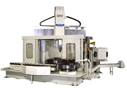
TUD series of CNC Vertical Boring and Turning Mills for unrivaled efficiency in boring and turning operation
Main features
High precision and heavy-duty machining
The thick-walled, cast Iron column and be is thermal symmetrically designed for high precision and heavy-duty machining
With an automatic tool-locking mechanism
The 220mm (8.66 in) square ram is solidly encased in a mono box structure which is incorporated with an automatic tool-locking mechanism
For Virtually all workpiece heights
A step positioning mechanism moves the crossrail a maximum 0f 500mm (19.6in) vertically in 250mm (9.84in) steps [750mm (29.5in) for TUD-20] for virtually all workpiece heights
Automation and labor saving
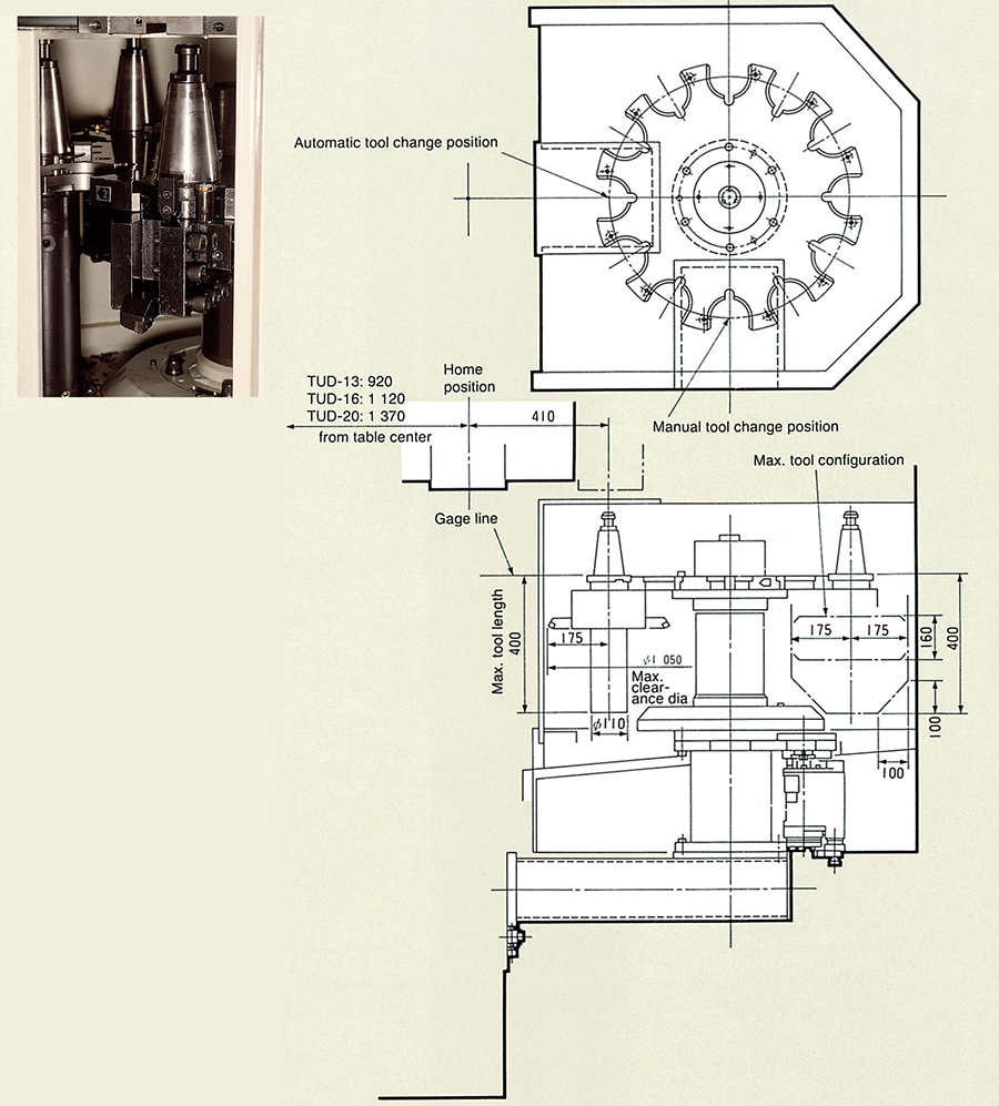
Special options, such as an automatic tool changer (ATC) and an automatic pallet changer (APC) are available for even greater degrees of automation and labor saving
Outstanding machine features for improved machining performance
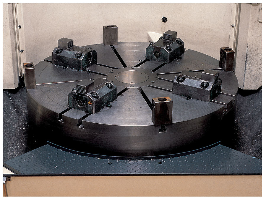
Table and bed
All of the major machine components are constructed of high-grade castings. The table has been provided with ample strength and size and is supported on a largediameter thrust ball bearing and tapered roller bearing arrangement. This type of arrangement assures adequate support fo extremely efficient, high speed heavy machining. In addition, the talbe is equipped with 4 independent manually-operated jaws and T-slots that guide and hold the workpiece in the required position.
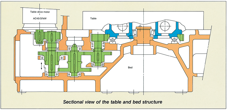
Thermal deformation is minimized by the standard-type lubricating-oil cooling system and the thermally symmetric layout of the machine bed which supports the table. Additionally, the table-drive mechanism is built into the rear section of the bed, and column is standing on the bed.
Independent manually-operated jaws
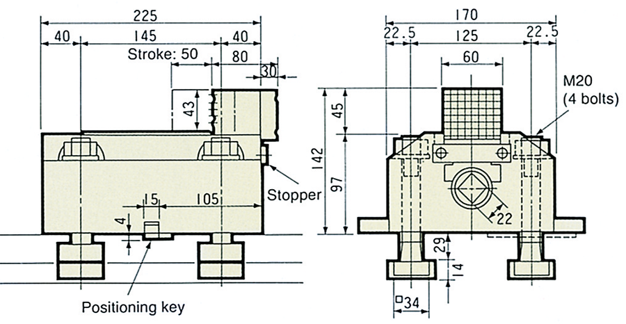
Four jaws with the following specifications are supplied as standard accessories.
- Maximum clamping force: 4 metric tons (8,800 lbs) (clamping torque 18.5 kgf-m [133 ft-lbs])
- Weight (one jaw): 28 kg (61.6 lbs)
Top view of table
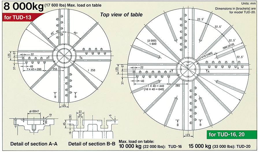
Table load-capacity diagram
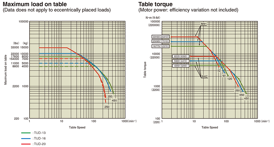
Table driving mechanism
The table is driven by a 2-step gear speed-change motor with a large-diameter helical gear located beneath the table. Speed changes are carried out by the 2-stage hydraulic shifting in combination with the variable speed AC motor. Excellent rigidity and minimum heat generation is assured by the simplified and thermally symmetric arrangement of the gear-train.
Column and crossrail
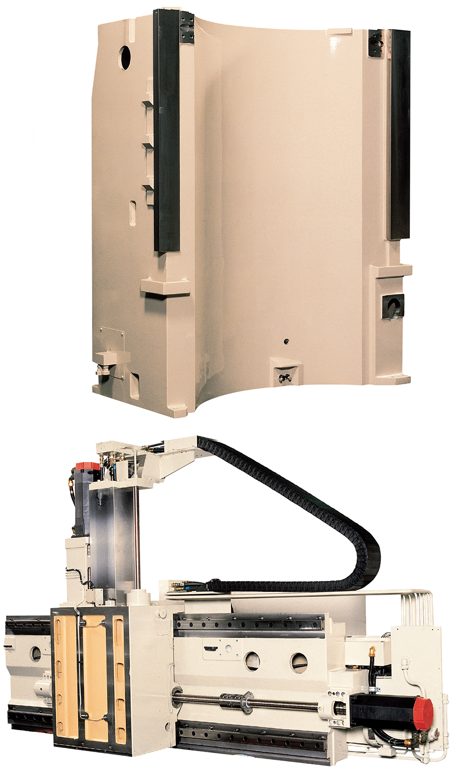
The column is a highly rigid symmetrical box-shaped structure that is provided with 2 slideways. The linear-guide on the crossrail is protected from chips and coolant by steel covers. The vertical travel of the crossrail is performed by a hydraulic cylinder in 250 mm (9.84 in) steps for precise positioning of up to a maximum of 500 mm (19.6 in) [750 mm (29.5 in) for TUD-20].
Rail head
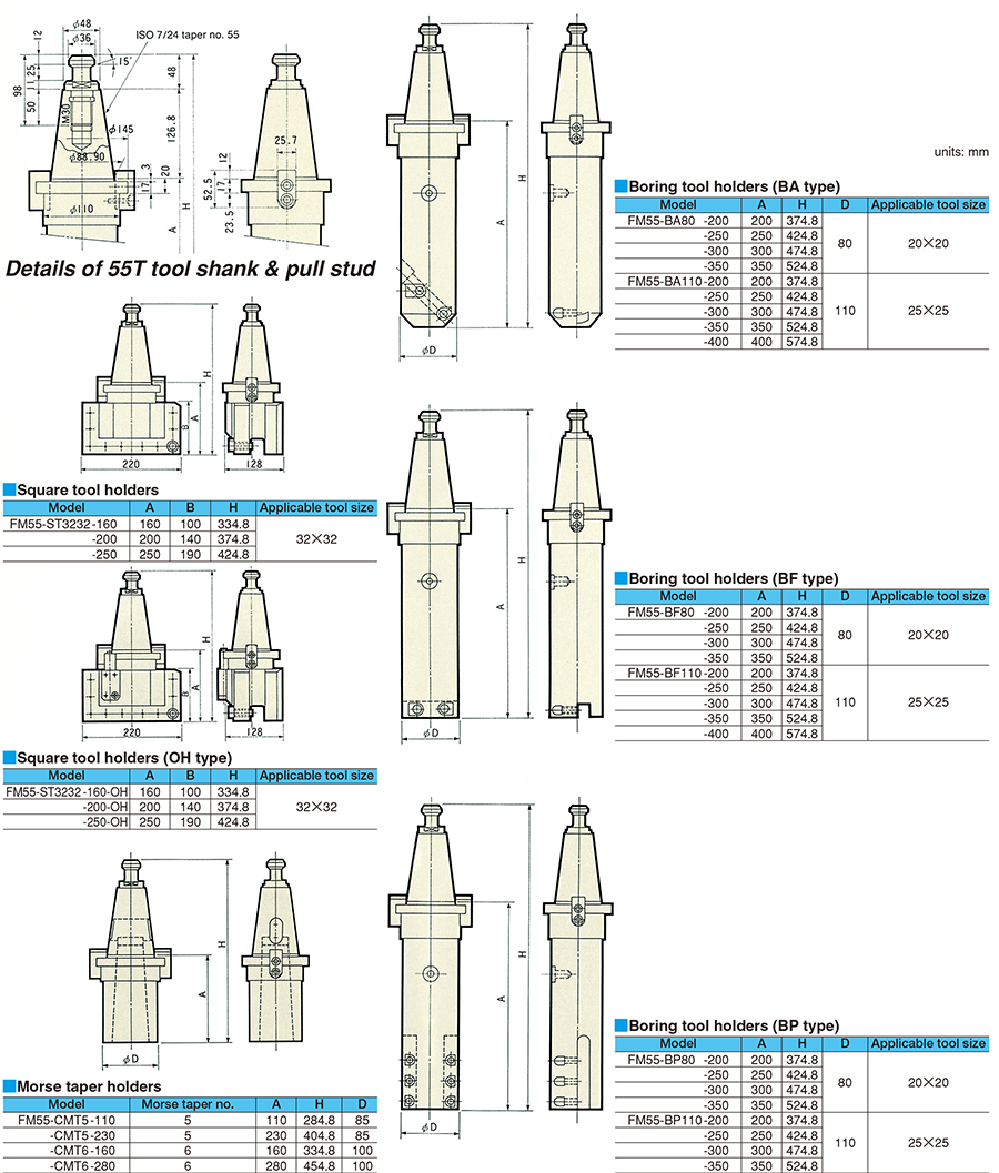
The 220 mm (8.66 in) square ram is securely supported on all 4 sides within a onepiece structure. Large-diameter ballscrews are employed for positioning in the horizontal (X-axis) and vertical (Z-axis) directions. Quick and precise positioning is possible by the special angular ball bearings supporting the ball-screws and the rolling linear guides for the X-axis slideway. The ISO No. 55 taper 7/24 and a collet-type pull-stud mechanism enables the clamping of tools on the ram automatically. Heavy duty cutting capability is assured by the powerful 6-metric ton clamping force.
| Machining example | |
|---|---|
| Cutting direction | X-axis← |
| Ram extension | 355 mm (14") |
| Machining diameter | 670 mm (26.4") |
| Table speed | Constant surface speed |
| Surface speed | 100 m/min. (328 sfm) |
| Depth of cut | 10 mm (0.4") |
| Feedrate | 1.3 mm/rev. (0.05"/rev.) |
| Material | S48C (carbon steel) |
| Estimated cutting force on ram | 2 600 kgf (5720 lbs) |
CNC Unit (FANUC Series 31i-B*)
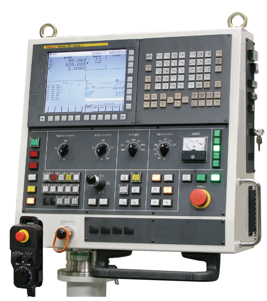
Efficient operation panel
-
Manual operations
These CNC-type machines can also be operated manually from the pendant panel which contains all the controls necessary for such operations as table movement, feed direction for horizontal and vertical movements, mode selection, and feed-rate and table-speed override. This pendant panel is also equipped with a manual pulse generator (MPG) for the observing of the toolpoint during machining in the same manner as that employed on conventional manual machines.
-
An abundant array of invaluable CNC functions for simplified and diverse machining operations.
Such useful functions as constant surface-speed control, fixed cycles for compound machining, and custom macros are available in a basic optional function package.
Note 1: M06, M55, M60, M80, M81 and M83, M84 are the M codes calling a custom macro.
Note 2: M56 and M57 are commanded during tool nose measurement (i.e., M06 or M55 mode). M63~M67 are commanded during tool change (M06) and need not be specified by the customer.

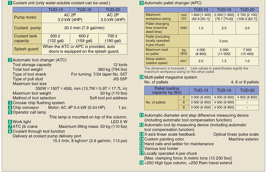
Basic Specifications
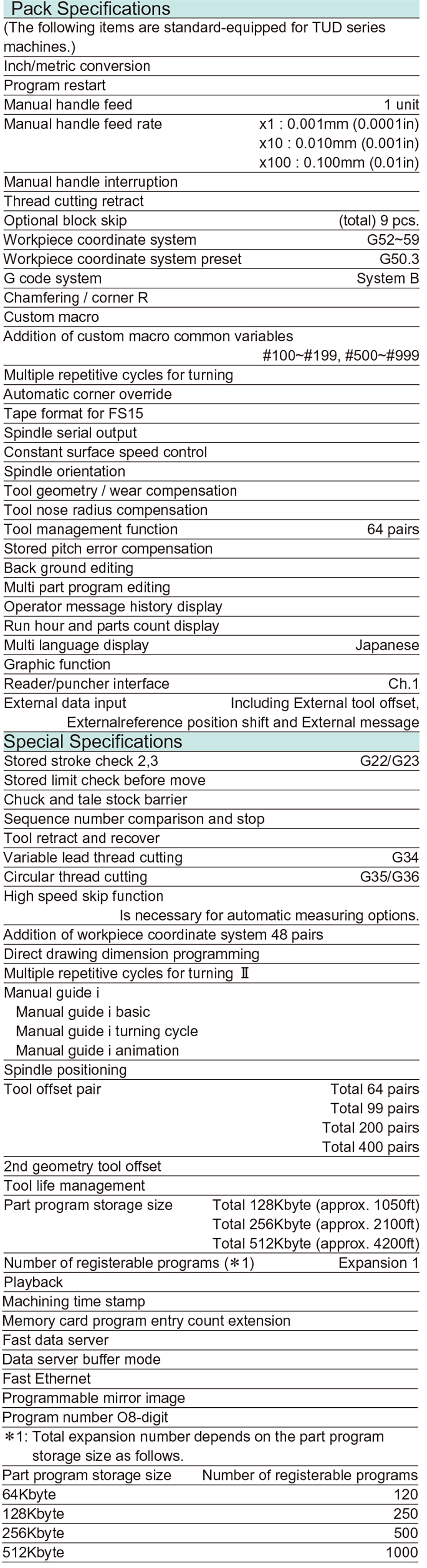
Optional Specifications
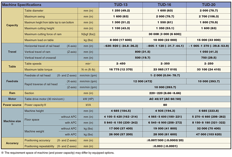
Specifications
An extensive line-up of peripheral equipment
Standard Accessories
- Installation parts 1 set
- Special service tools 1 set
- Chip guard 1set
(When a coolant unit is provided,splash guard serves also as a chip guard.) - Automatic slideway lubricating unit 1set
- Crossrail step-positioning unit 1set
- Locally operated 4-jaw chuck [Max clamping force: 4 metric tons (8800 lbs)]
(When an APC is provided, jaws included in a pallet serve also as a chuck.) - Telescopic crossrail slide cover 1set
- Automatic power OFF device 1set
- Table lubricant oil cooling unit 1set
Optional Accessories
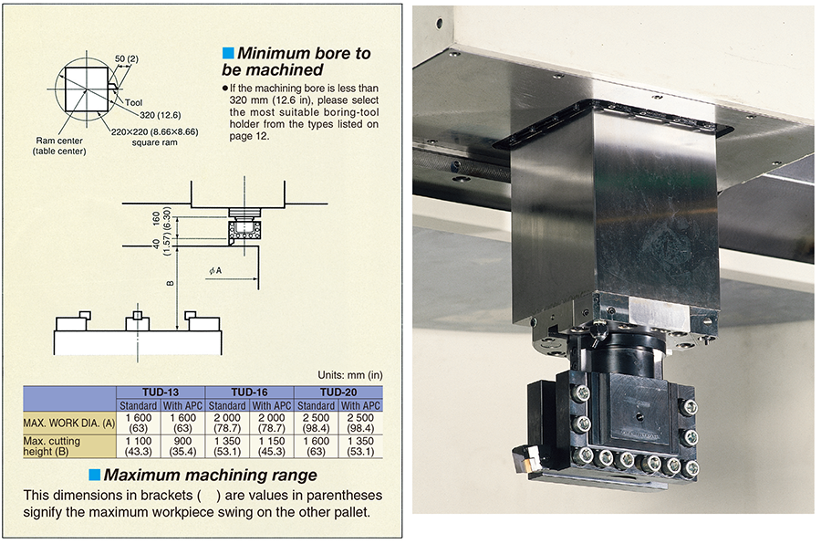
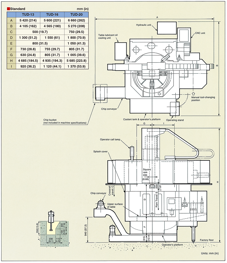
Machine dimensions
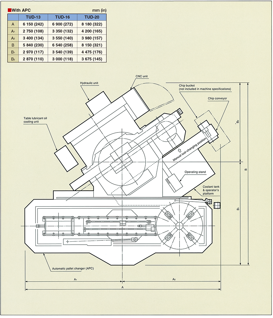
Machine dimensions with APC
Automated functions (optional)
Automatic tool measuring unit
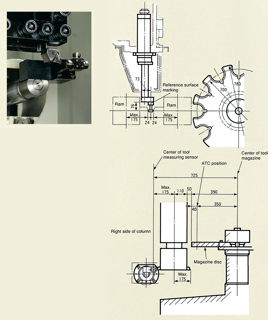
Automatic tool changer (ATC)
Tool holders (optional)