MP-2620(U)
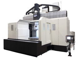
SHIBAURA'S ADVANCED TECHNOLOGIES have been focused on our bridge type multi-purpose machine.
Main features
Turning operation
Milling operation
Integral feature
Machining center, vertical turning center, and as a 5 axis machine when selecting the optional spindle head. The overall design of this machine is an integral feature to also process an extensive range of machine parts.
High speed, high rigidity and high accuracy
"All linear axis X, Y and Z are designed with twin drive mechanism in order to achieve high rigidity and high accuracy. This attribute allows swift machine motion even at 40m/min in rapid and 20m/min in cutting feed mode."
Features of the machine
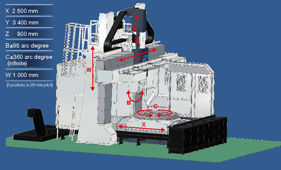
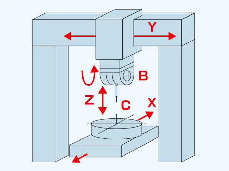
Axis configuration
The standard machine has 4 axes which consist of three (3) linear axes of X, Y, and Z, and one (1) rotary axis C.
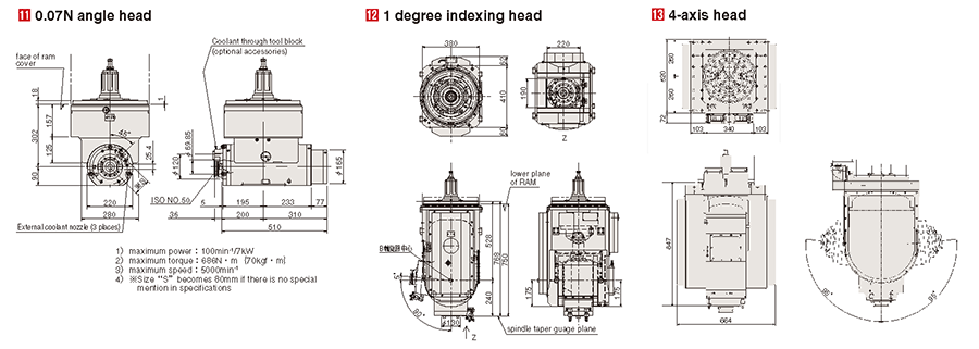
A 4-axis head in an (optional accessory) for 5-axis machining.
The W axis is a crossrail that can be located at 5 positions is 250mm increments.
Productivity
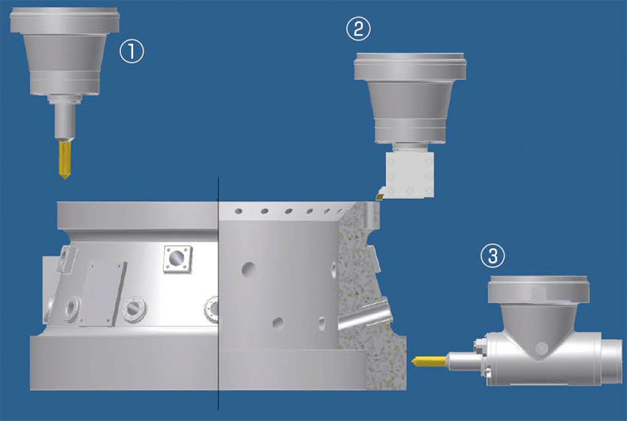
Several kinds of attachments make the machine a multi-purpose machine.
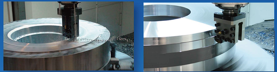
The Snout 240 can be used for boring and turning operation as shown in figure 1, and 2.
The angle head can be utilized for machining the side of a workpiece as shown in figure 3.
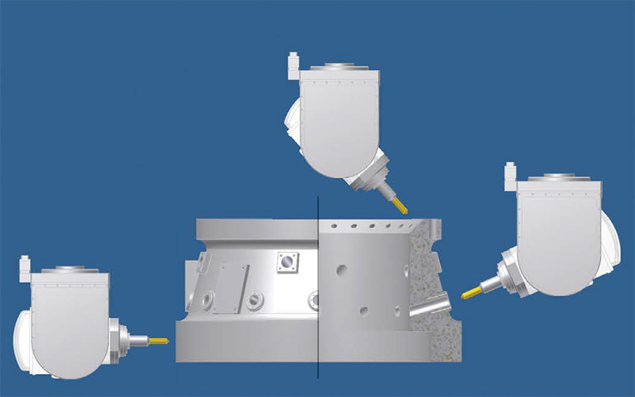
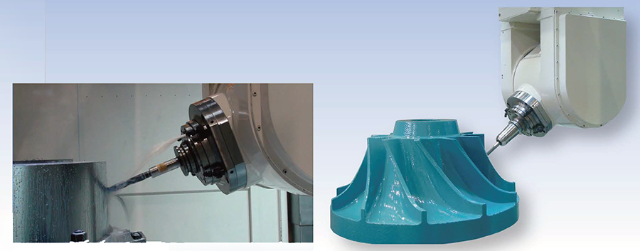
4-axis head is shown for machining on any inclined surface.
Accessibility
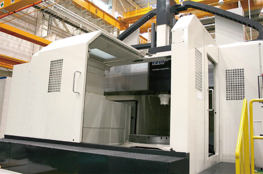
Chip cover with ceiling
The chip cover with ceiling enclosure is standard accessory, and the L-shape door with ceiling compliment an ergonomic design, enabling easy access to the area around the table.
Axcellent chip discharge around a wide enclosure.
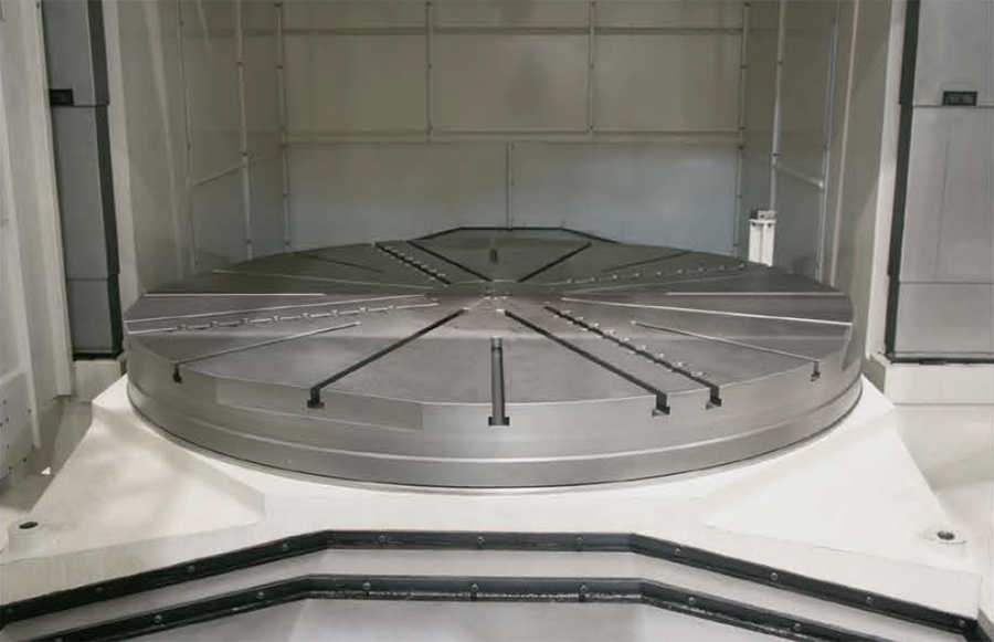
Wide space and easy chip discharge around the table
A round rigid table is utilized turning and milling operations for both turning and milling operations.
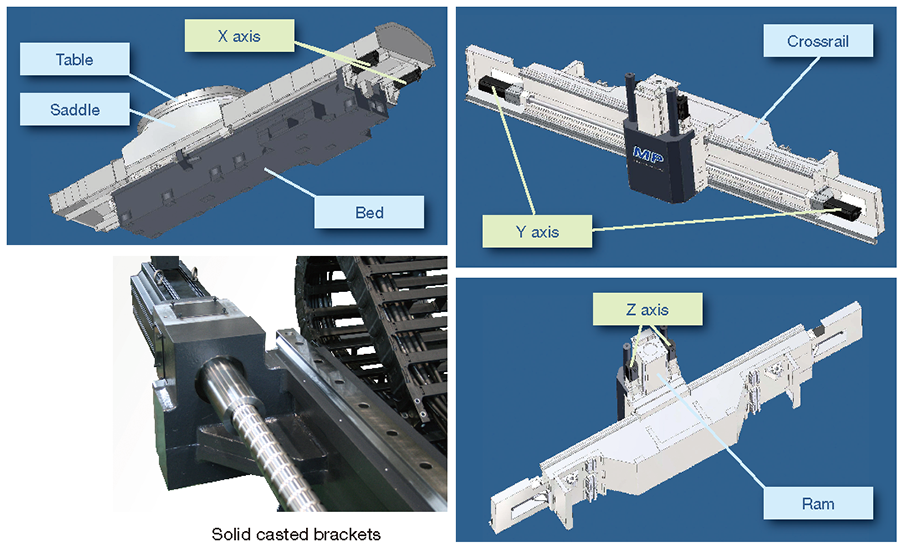
Swift motion, high rigidity, high accuracy
The twin drive mechanisms on all linear axes assure swift motion, high rigidity, and higher accuracy on the machine.
Solid casted brackets support ball screws on all linear axes to assure high positioning accuracy.
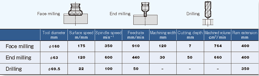
Present its full capability
Milling capability
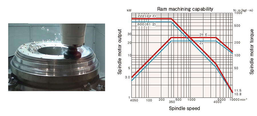
Material: S55C(machined with the “Snout 240”)
Turning capability
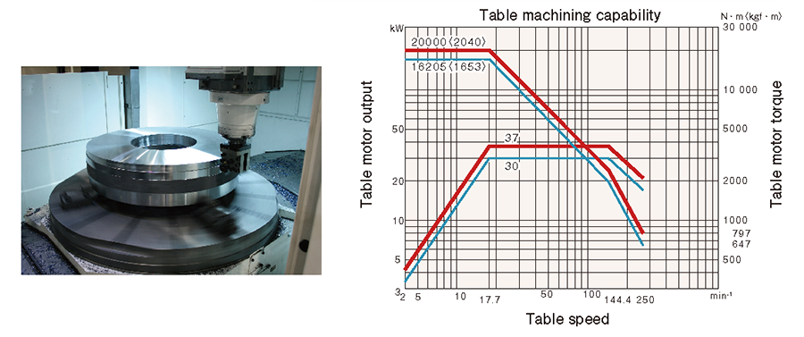
Material: SS400(machined with the “Snout 240”)
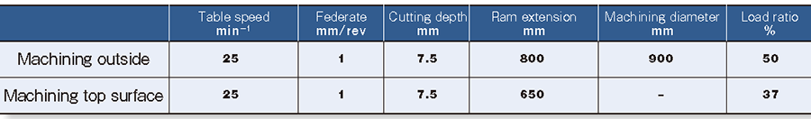
Table configuration
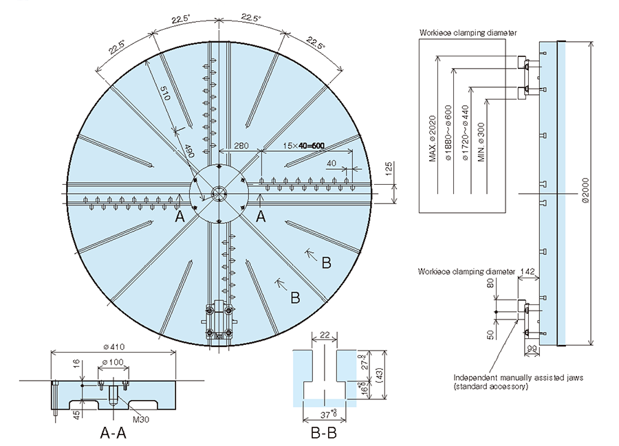
Manually assisted independent jaws (4 sets)
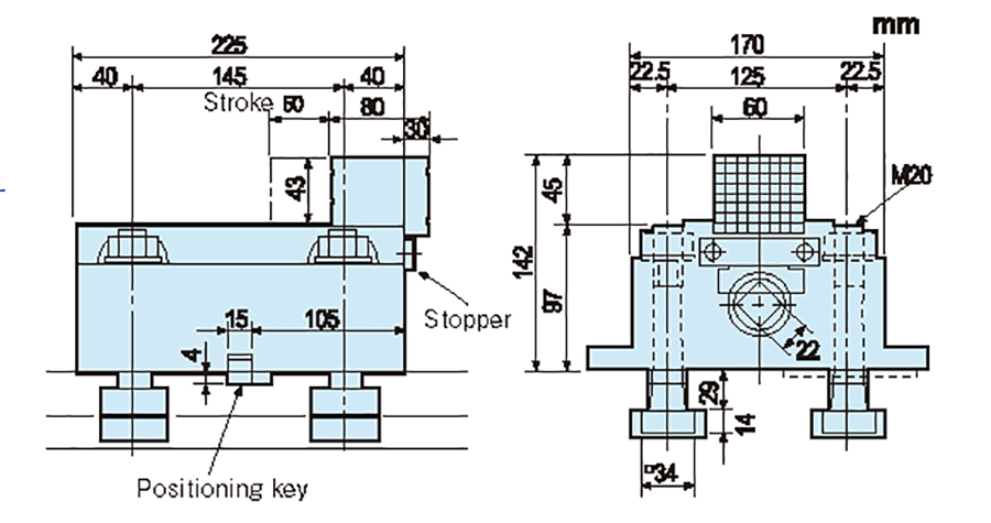
・Maximum clamping force : 4 tons,
(18kgf-m clamping torque)
・Mass of a unit ; 28 kg
Cautions on turning operation
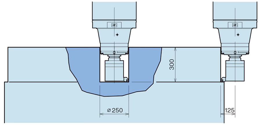
Table configuration Turning depth on a square type tool holder some restrictions “on a case-by case basis” please consult us for further detail.
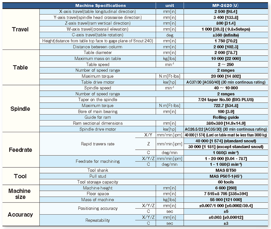
Machine Specifications
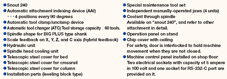
Standard accessories
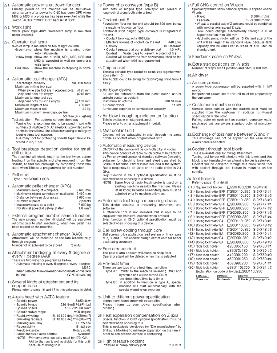
Optional accessories
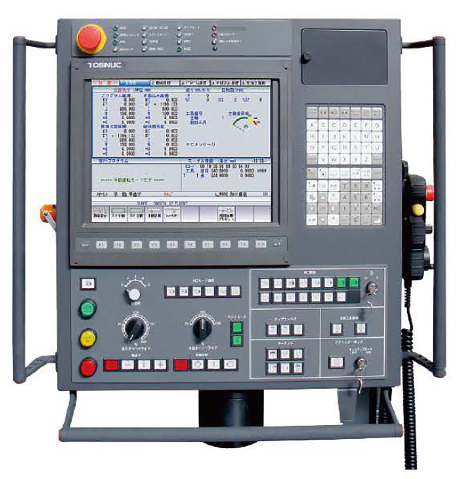
TOSNUC PX100 STATE OF THE ART CNC CONTROLLER DEVELOPED TO MAXIMIZE MACHINE PERFORMANCE & PROFITS.
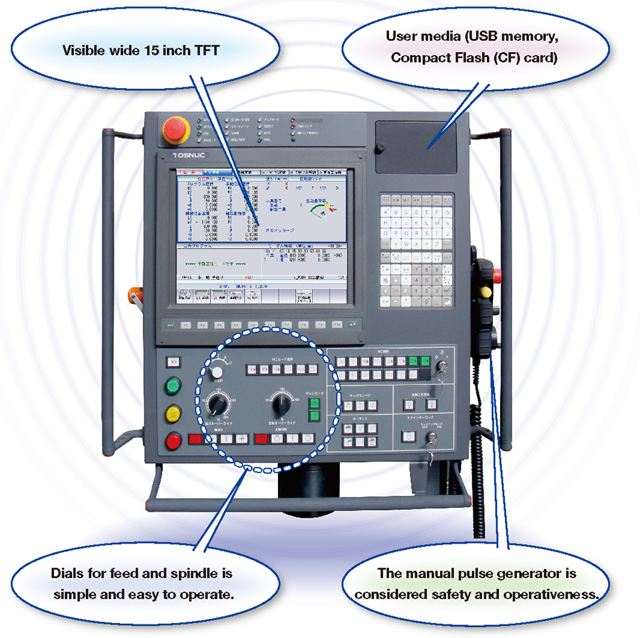
TOSNUC PX100
TOSNUC PX100, A personal computer architecture. Integrated into our TOSNUC controller developed specifically to enhance our CNC controller with higher performance functions and even nore versatility.
Our goal to create more innovative features that support easier operation thus contributing to an increase in productivity and machine performance.
Versatility in operation based on our vast experience
Based on our extensive experience integration between mechanical and electronic technology. Our new CNC controller was developed with an emphasis on easy operation, easy to understand and easy to remember.
This perfect combination is the Key to achieving higher machining accuracy in high speed machining.
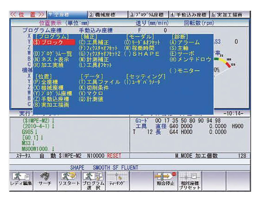
Pop-up menu
By pressing a soft key on the selected screen a menu will appear showing the desired function on a sub display window.
Having a pop up display menu type system avoids complicated hierarchy in software and shortening the scan time to process a desired function.
File editing screen
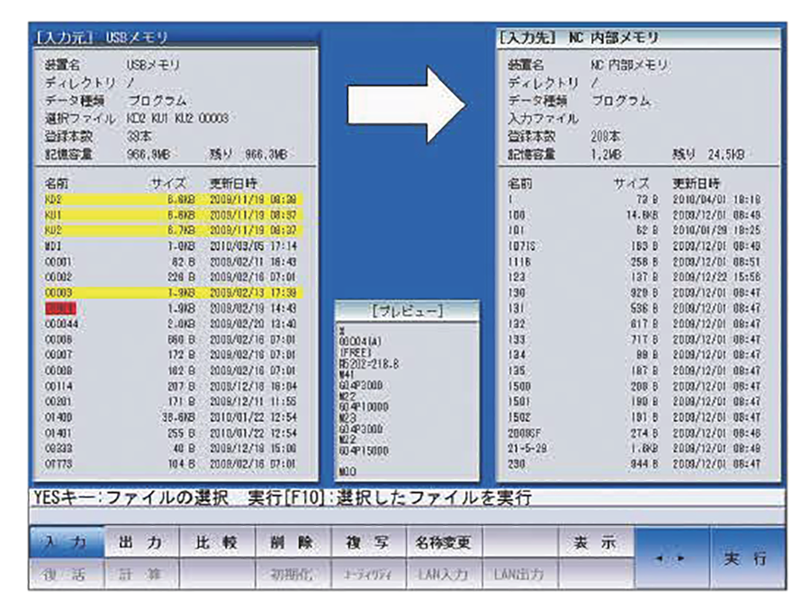
Multi-task and multi-window is a feature that enables you to open a window file from any current screen to perform program input/output deleting or copy a program to execute a calculator screen clipboard.
Program list and memory are connected to a user media and displayed on the screen allowing the program to be checked in a preview window within the same screen during input or output of programs from a user media.
Multi screen background edit
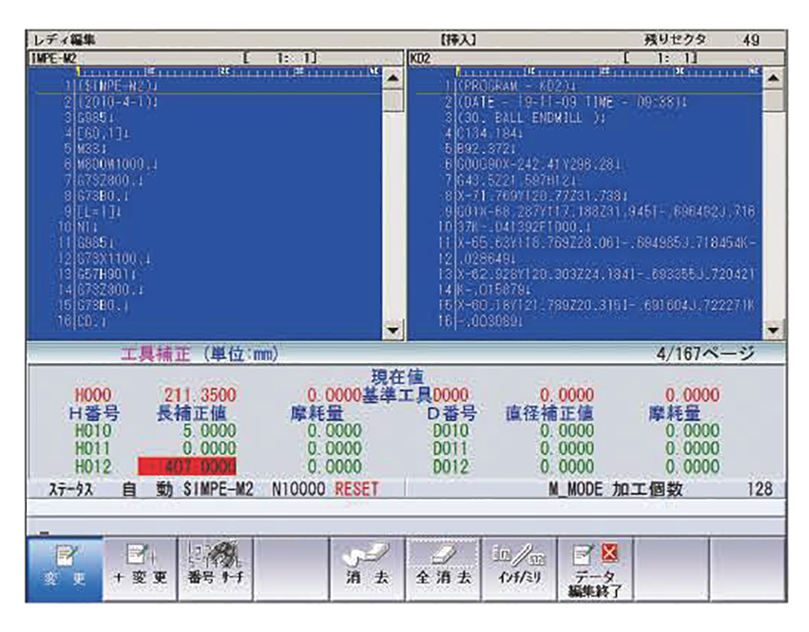
The screen can be divided into three sections to display two program screens and the third shown MODAL OFFSET DATA compensation information which is required upon machining.
These three screens run independently during automatic operation and during editing.
A new program can be generated and created utilizing a clipboard feature and or background split screen edit two programs simultaneously as compared to a personal computer.
Program support functions
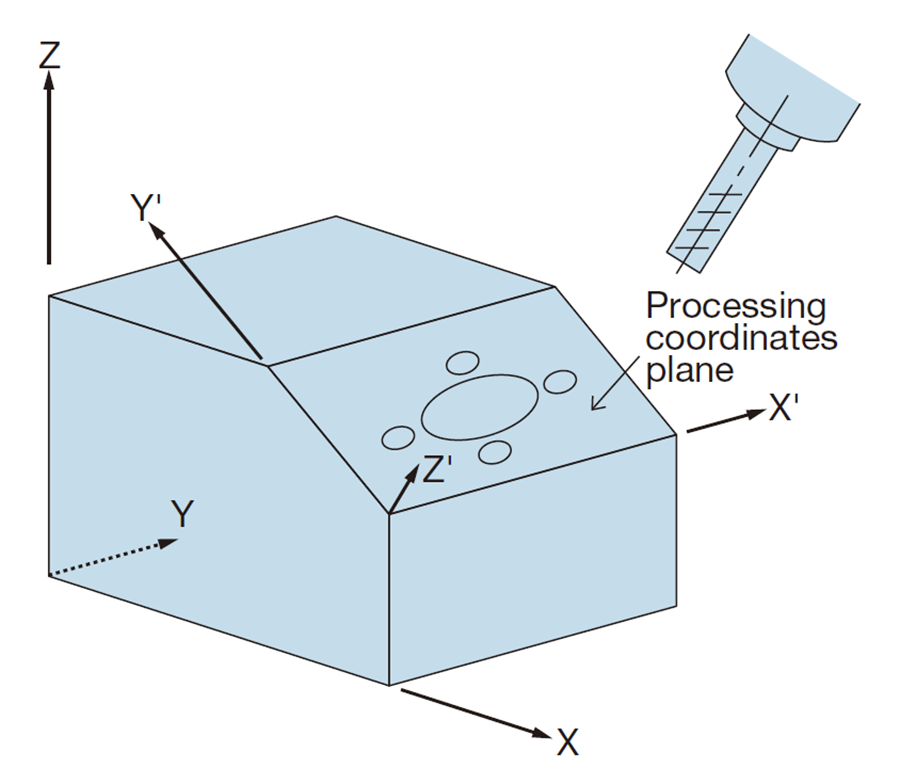
A general program running on G17 plane when programmed on X-Y plane and machining a depth on inclined surface as shown does not require a program modification. This very important feature convenient and executable with G command and canned cycle simplify machining of an inclined surface without effort.
Advanced functions for high speed machining and
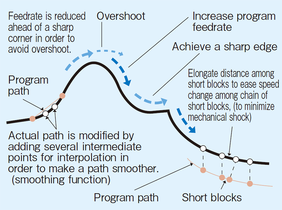
Preview control
Generally a profile that is being machined will require a true shape. Shape error decreases as servo gain increases. However a high servo gain causes overshoot and increases machine vibration causes from large.
Acceleration to the mechanical components or system which in turn causes a bad surface finish during machining.
Preview or SHAPE CONTROL is based on the optimum control theory developed specifically to prevent such an outcome.
This important development prevents such an effect on countoured surfaces and minimizes shape error without the need for a high gain servo system.
Tool contact point control
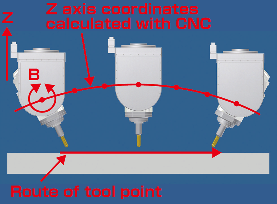
Program path must be the path of tool position changes during rotary axis motion. Actual compensated command of each axis is calculated out from tool and nachine data and program path.
This important feature is key in preventing tool path error due to change of tool position on rotary axis.
Tool nose position compensation
This will compensate several errors and offset on mechanical construction.
In the case of MP-2620(U), there could be errors in followings.
- Inclination of C axis center line to X axis
- Inclination of C axis center line to Y axis
- Inclination of B axis center line to X axis
- Inclination of B axis center line to Z axis
- Offset between B axis center and spindle center in X axis direction
CNC specifications TOSNUC PX100
Various kind of Attachments
Standard accessory
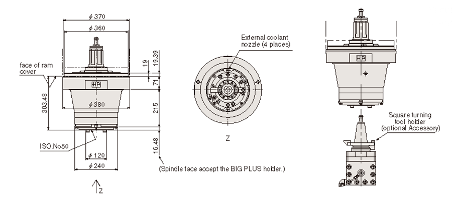
Snout 240
Optional attachment
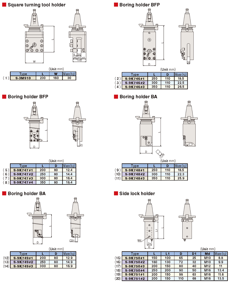
Turning Tool holders (optional accessory)
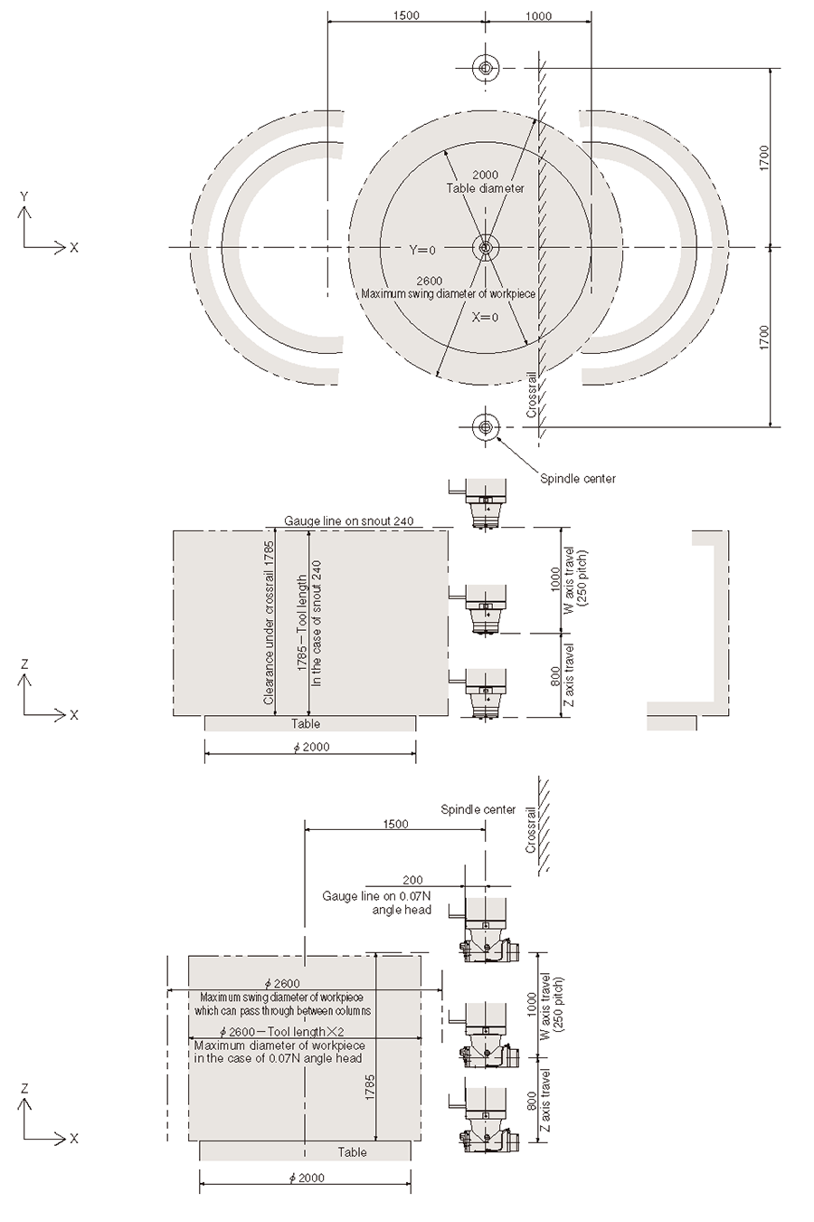
General view and Layout
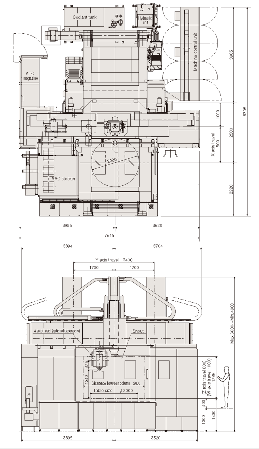
Large and wider machining space