MCW-4624
New concept machine that is highly cost effective and assures higher productivity and performance
Innovation in manufacturing
Minimal floor space in the processing of large workpieces
Installation area is minimized to rectangular shape which allow a 75% saving in space when compared of a conventional type table travel machine 4.9 meter machine height is beneficial when confronted with a factory that has a low ceil
High accuracy & High rigidity
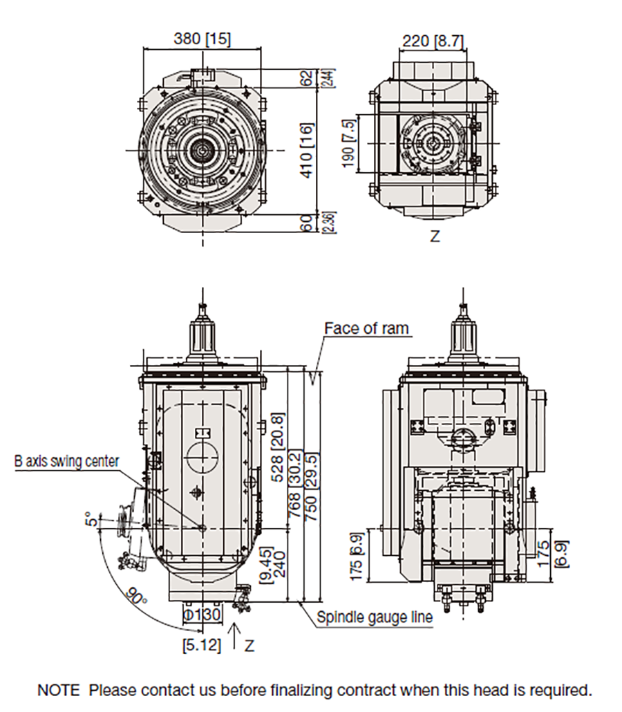
Crossrail, which travel on wall column, is supported by two rigid and stable saddles and has low gravity center to assure high accuracy and rigidity. Mono-block casted spindle head has full closed carefully adjusted guide for square ram (ram section is 380 x 380mm).
Features of the machine
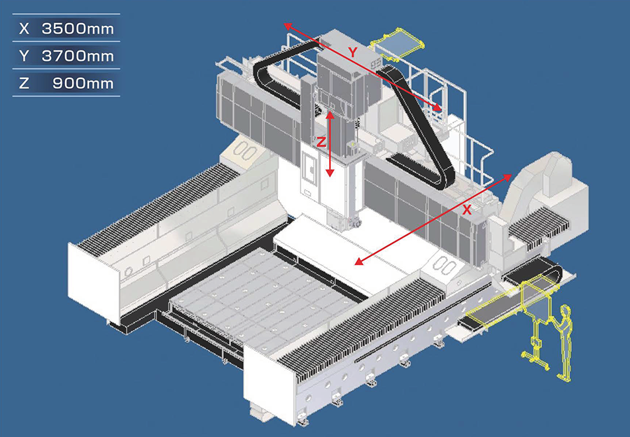
Axis configuration
Better Accessibility & Easy Chip Discharge
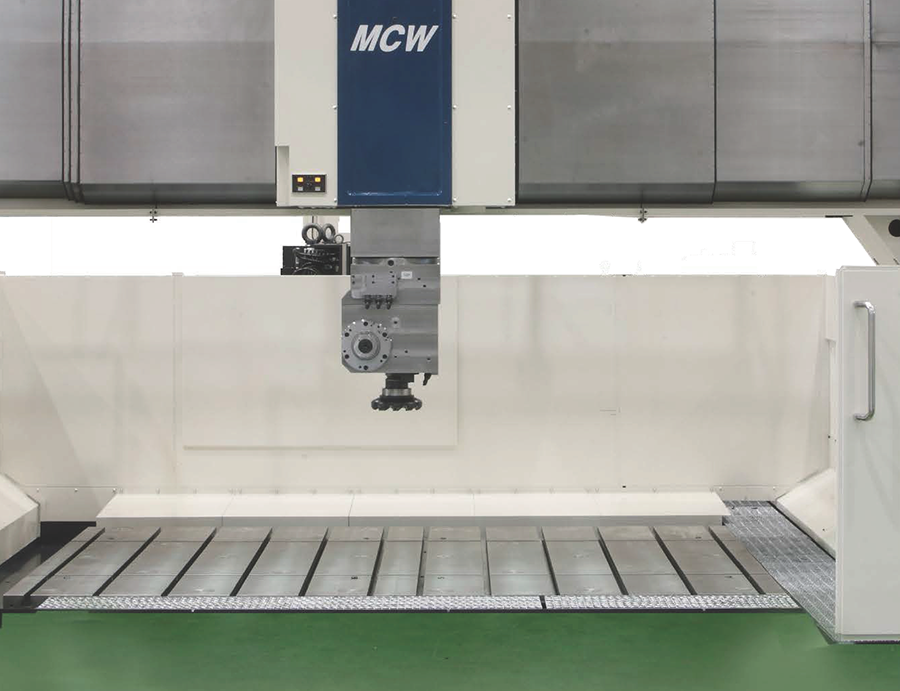
- Table top is the same as the shop floor level eliminating steps in order to give the operator bellow accessibiling and efficiency in operation.
- The table parameter has a chip chute or chip conveyor to facilitate easier chip removal.
- Wall columns plevent chips from accumulating around the machine and are located along both sides of the table in the longitudinal direction supported by guide-ways for bridge travel in the X direction.
High accuracy & High rigidity
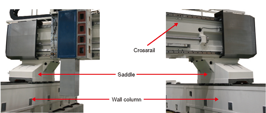
Rigid and stable movement in positioning is derived from crossrail configuration.
Crossrail, which travel on wall column, is supported by two rigid and stable saddles and has low gravity center to assure high accuracy and rigidity.
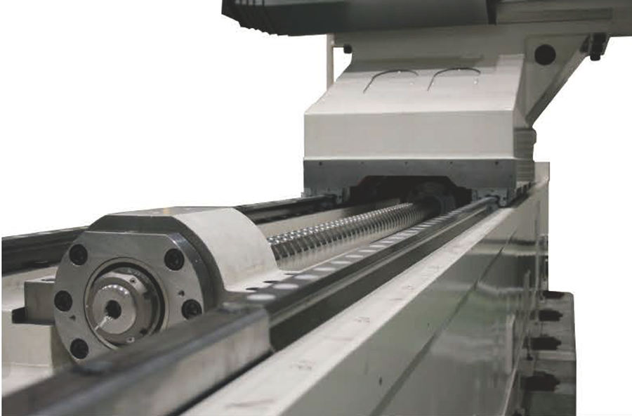
Each of master side saddle (left) and slave side saddle (right) are guided on two roller type rolling guideways and fed by ball screw located at center of them to assure high accuracy.
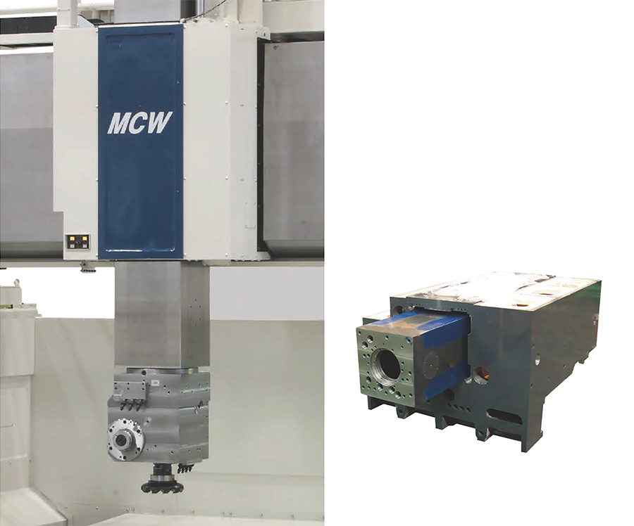
Mono-block casted spindle head has full closed carefully adjusted guide for square ram (ram section is 380mm x 380mm) (left) and Mono-block casted spindle head with buit-in ram guideway (right).
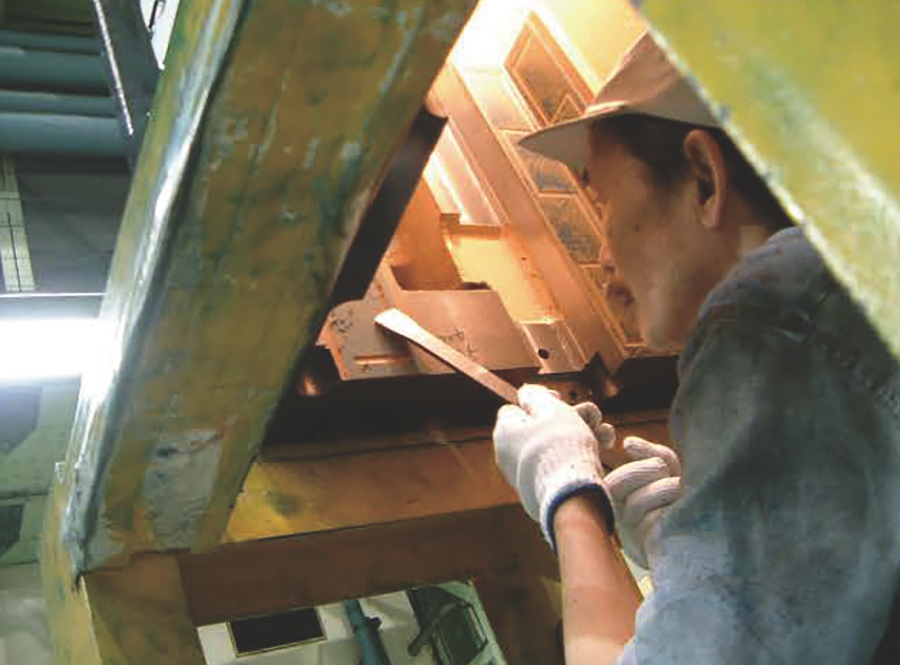
Hand scraping on ram guideway.
Versatility
Several variations and layouts are available from the basic construction of the machine to a combination of basic machine and configuration with special attachments and optional accessories as shown below.
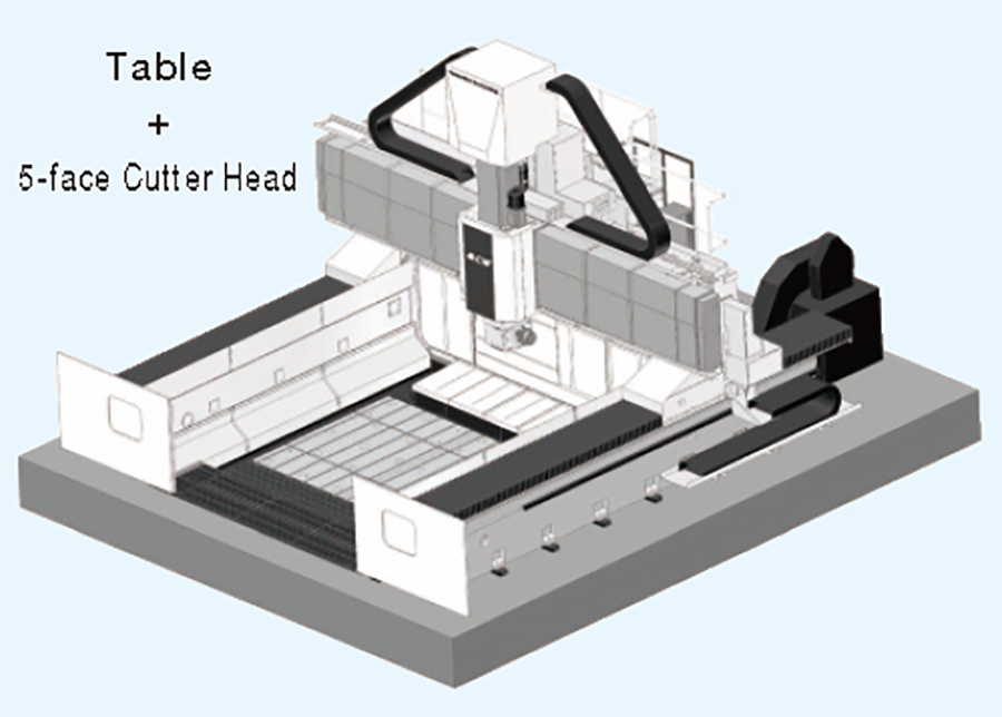
Standard Layout
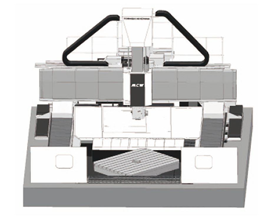
Example 1:Integrated Rotary Table
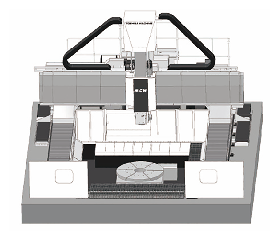
Example 2:Additional Portable Rotary Table
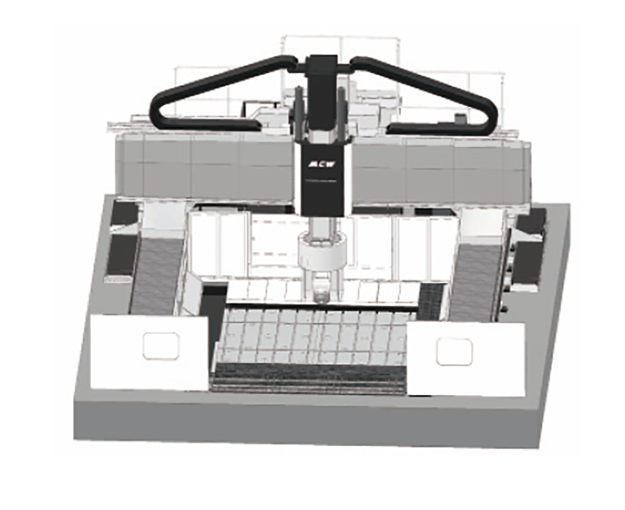
Example 3:Optional 5-axis Head
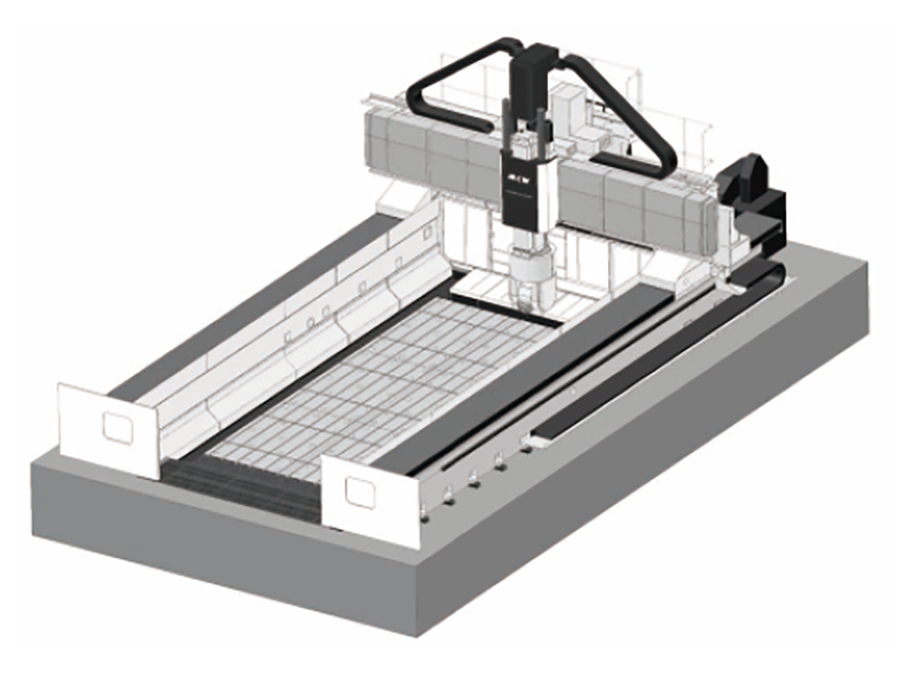
Example 4:Extended X Travel and Optional 5-axis Head
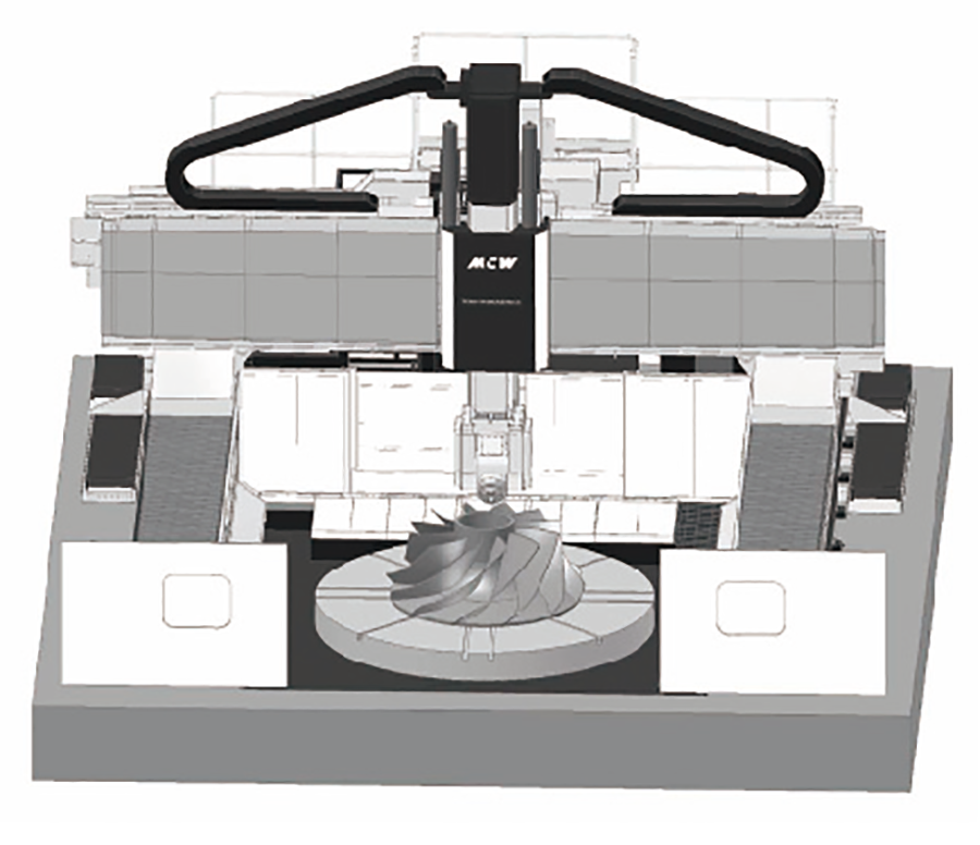
Example 5:Integrated Turning Table and Optional 4-axis Head
Machining capability (5-face Cutter Head)
Machining capability table
Machining example (Sample data)
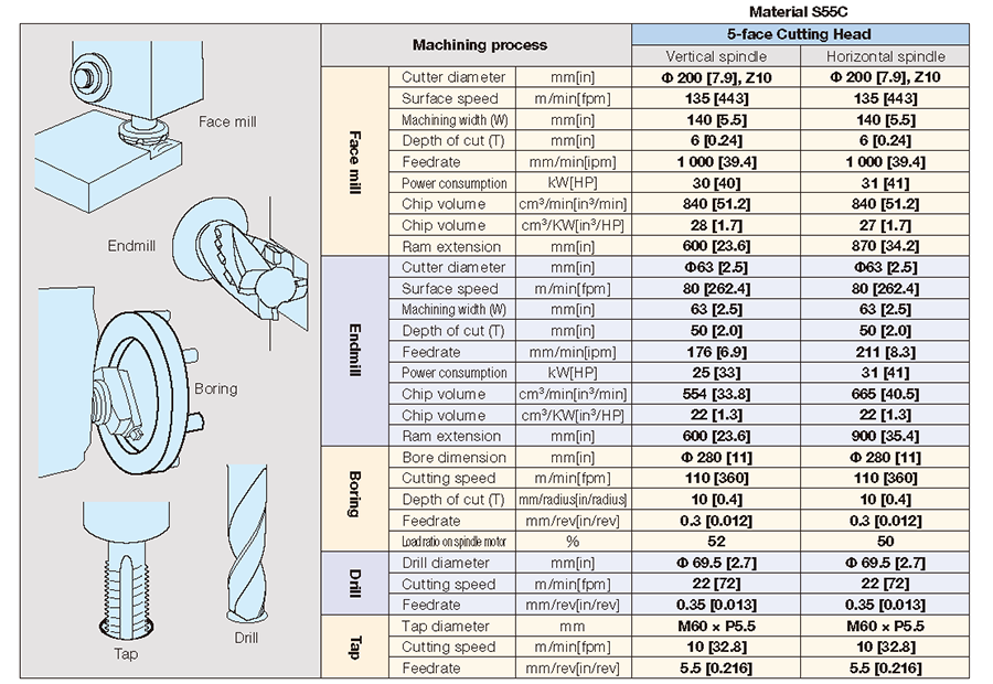
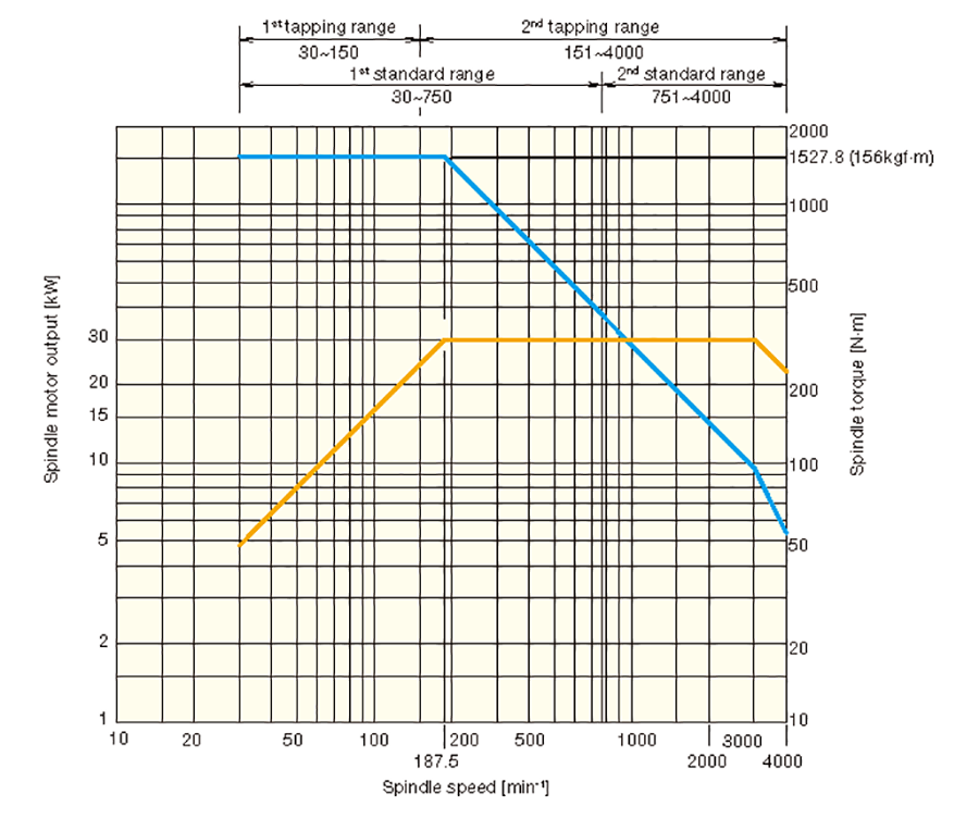
Torque and power diagram
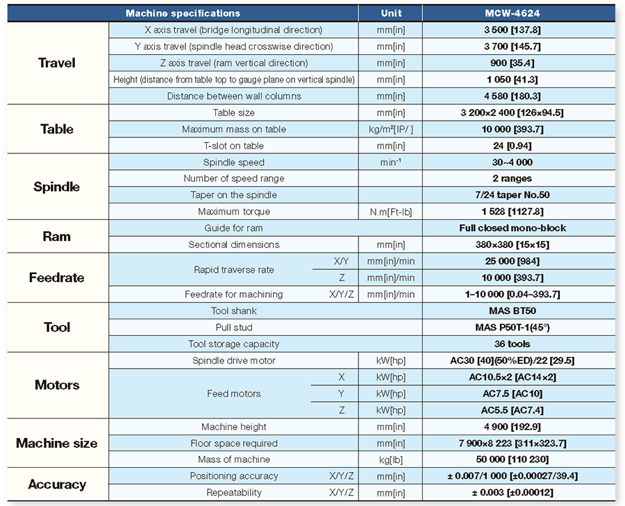
Machine Specifications
Standard accessories
- Automatic attachment indexing device (AAI) : at 4 positions every 90 degree.*
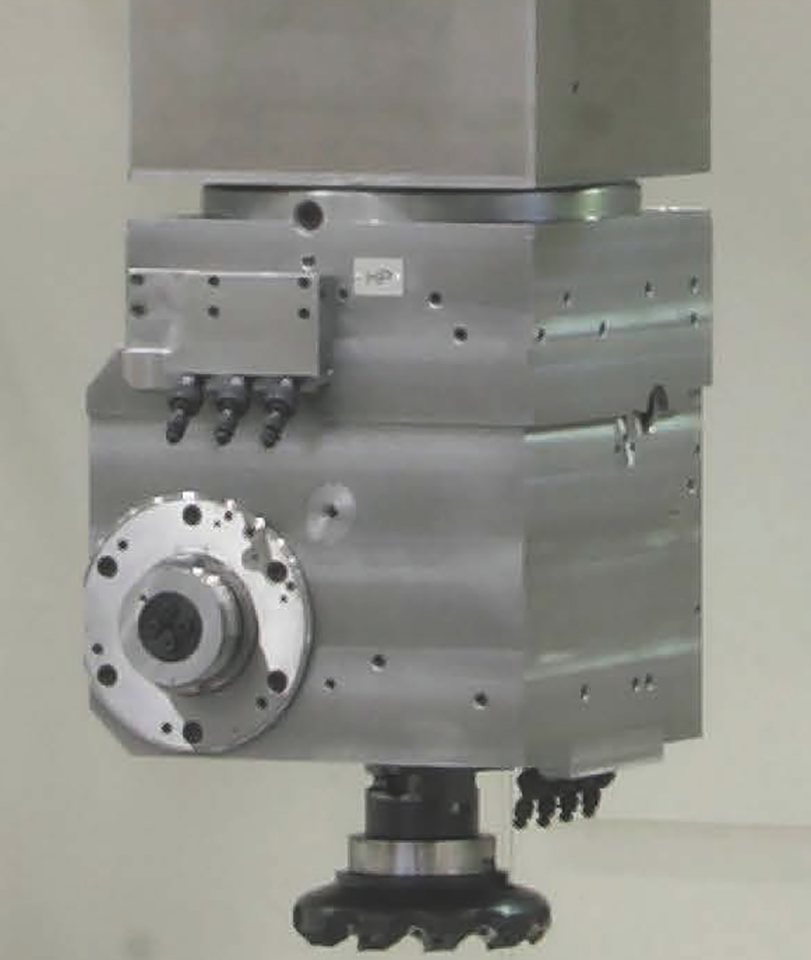
- 5-face cutter head*
- Automatic tool changer (ATC) ; 36 tools.*
- Bellows type wall column covers for X-Axis
- Telescopic steel cover for bridge
- Special maintenance tool set
- Hydraulic ram balance cylinder
- Automatic tool clamp/unclamp device
- Oil mist lubrication unit for gears
- Oil mist lubrication unit for bearings
- Hydraulic unit
- Ram slideway (Z-axis) lubrication unit
- Electrical outlet for external devices
- Operation panel on stand*
- ATC cover
- Chip cover at table end behind the machine
- Coolant and chip chute along table longitudinal sides
- Coolant and chip chute at front and rear end of table
Note : Standard accessories marked with “* ” shall be deleted, when a relevant optional accessory is selected in stead of the standard accessories.
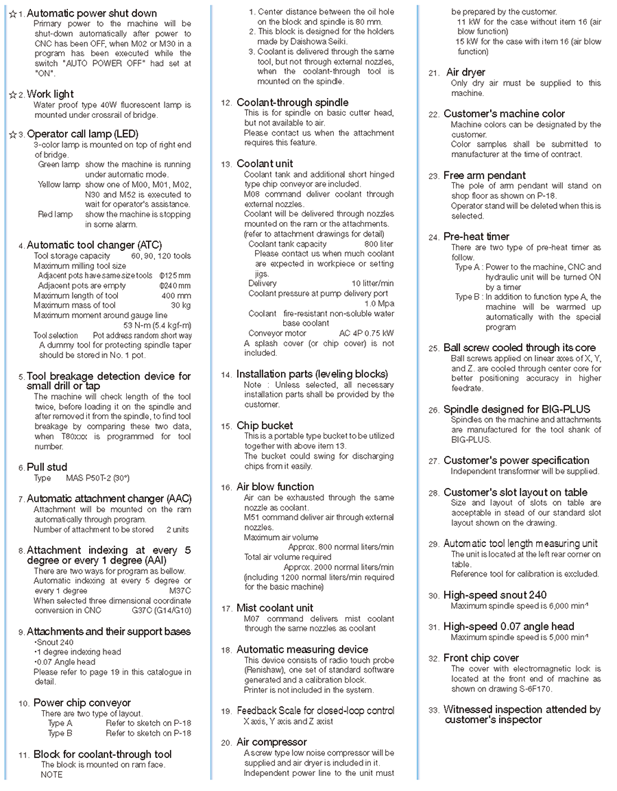
Optional accessories
(Items marked with ☆ are included in the pack specifications.)
TOSNUC PX100
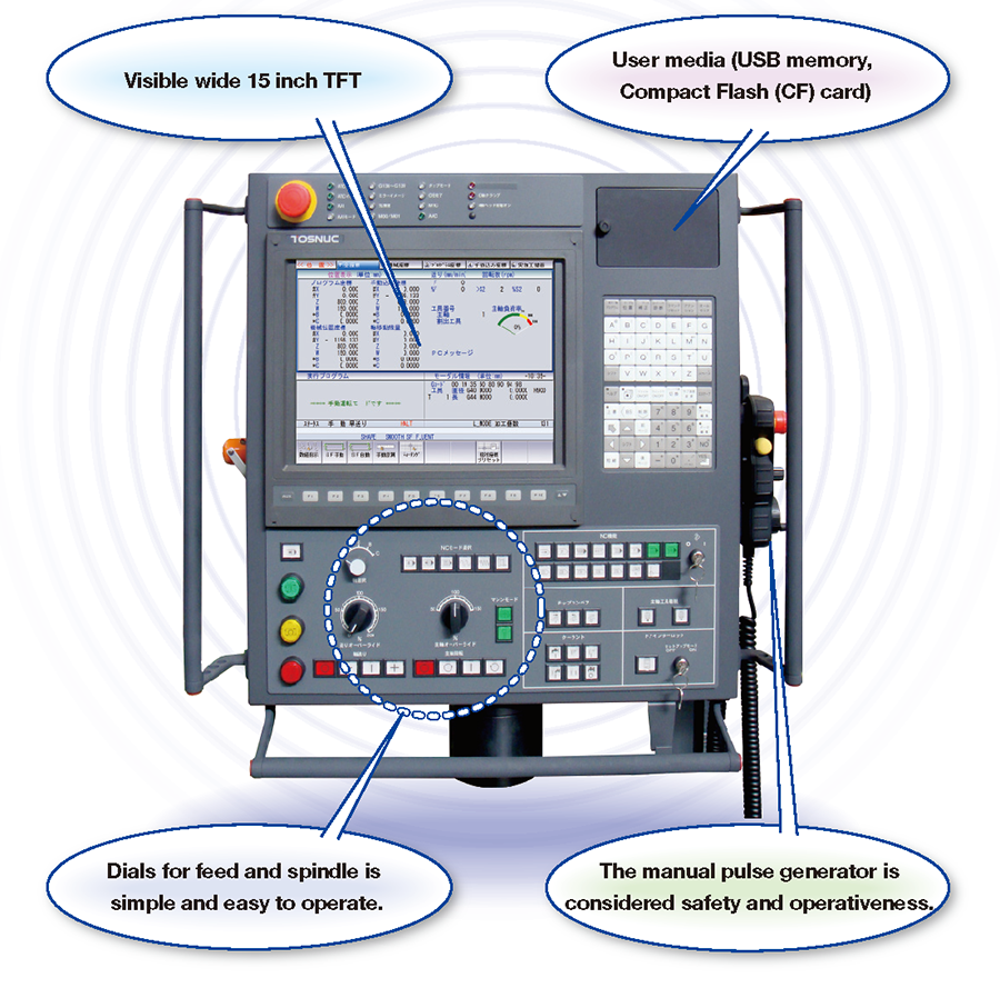
TOSNUC PX100 STATE OF THE ART CNC CONTROLLER DEVELOPED TO MAXIMIZE MACHINE PERFORMANCE & PROFITS.
TOSNUC PX100, A personal computer architecture. Integrated into our TOSNUC controller developed
specifically to enhance our CNC controller with higher performance functions and even more versatility. Our goal to create more innovative features that support easier operation thus contributing to an increase in productivity and machine performance.
Versatility in operation based on our vast experience
Based on our extensive experience integration between mechanical and electronic technology. Our new CNC controller was developed with an emphasis on easy operation, easy to understand and easy to remember. This perfect combination is the Key to achieving higher machining accuracy in high speed machining.
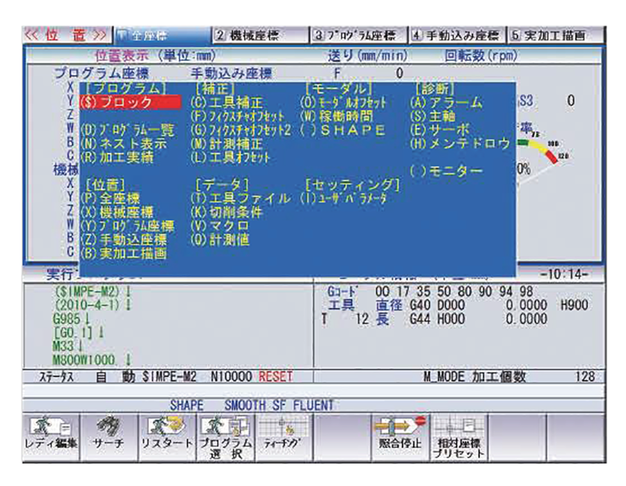
Pop-up menu
By pressing a soft key on the selected screen a menu will appear showing the desired function on a sub display window. Having a pop up display menu type system avoids complicated hierarchy in software and shortening the scan time to process a desired function.
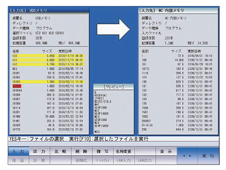
File editing screen
Multi-task and multi-window is a feature that enables you to open a window file from any current screen to perform program input/output deleting or copy a program to execute a calculator screen clipboard. Program list and memory are connected to a user media and displayed on the screen allowing the program to be checked in a preview window within the same screen during input or output of programs from a user media.
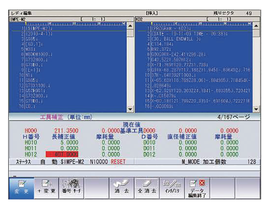
Multi screen background edit
The screen can be divided into three sections to display two program screens and the third shown MODAL OFFSET DATA compensation information which is required upon machining. These three screens run independently during automatic operation and during editing. A new program can be generated and created utilizing a clipboard feature and or background split screen edit two programs simultaneously as compared to a personal computer.
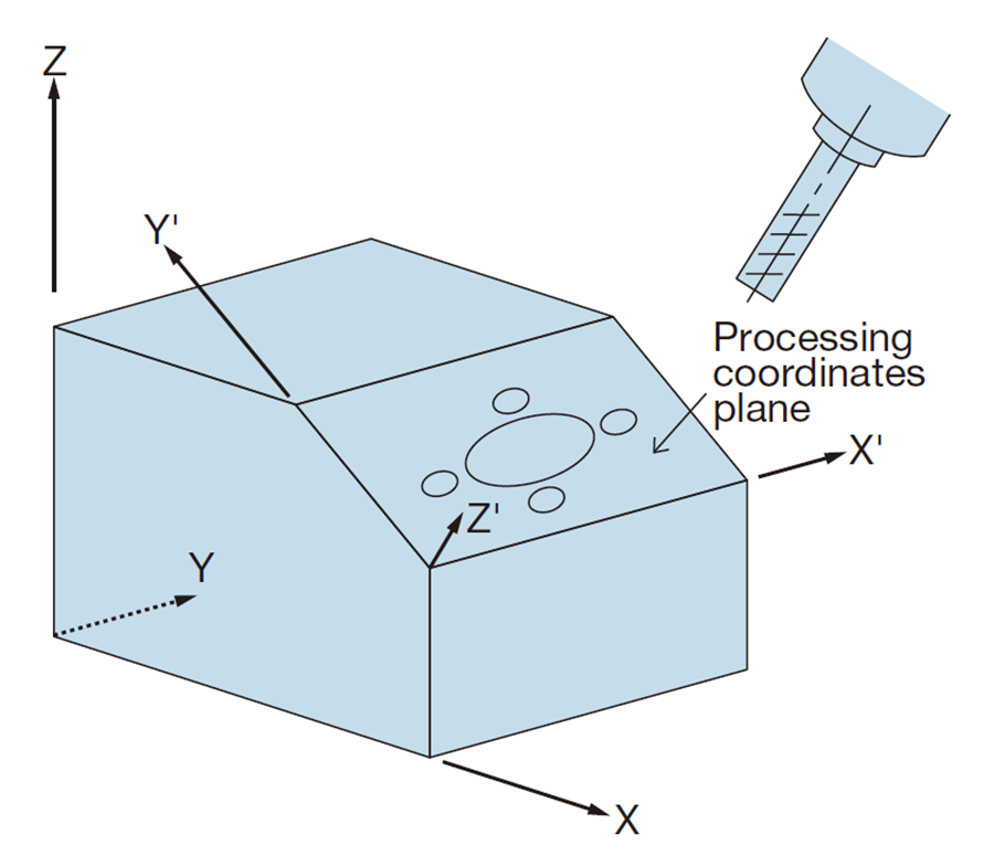
Program support functions
A general program running on G17 plane when programmed on X-Y plane and machining a depth on inclined surface as shown does not require a program modification. This very important feature convenient and executable with G command and canned cycle simplify machining of an inclined surface without effort.
Advanced functions for high speed machining and higher machining accuracy
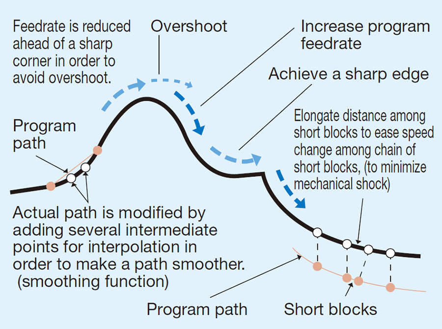
Preview control
Generally, a profile to be machined requires a true shape and shape error decrease as servo gain increase. However high gain causes over shoot and increases machine vibration from large acceleration to mechanical system, which causes a bad surface finish in machining. Preview control based on optimum control theory is developed to prevent such affect on machined surface and minimize shape error without setting high gain.
Graphic machining simulation
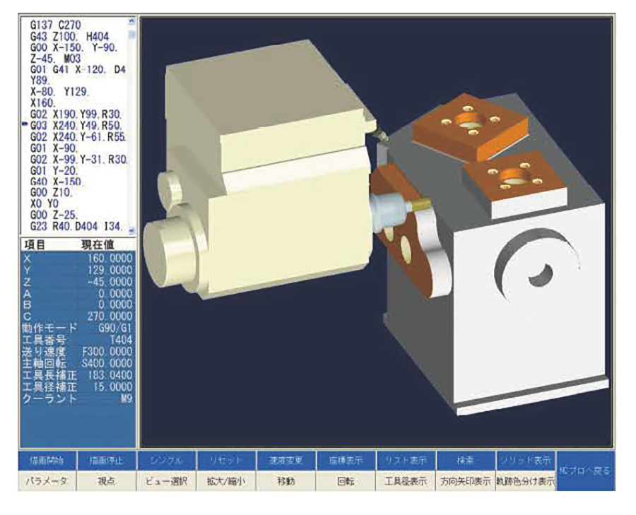
PX100 graphic simulation
Simulation of a created program is executed on the screen, after starting the program editor on TOSNUC PX100.
- This simulation function utilizes solid wireframe method.
- Format check feature is integrated to check a program beforehand starting machining.
(Including machining time estimation function) - Interference between workpiece and tool is checked by this, and the final shape of the workpiece is checked by utilizing Preview control function, which might be caused by program errors.
- The macro program created by the customer is checked by plotting with "MACRO DEBUGGER" function.
CNC specifications TOSNUC PX100
CNC specifications(PDF/149.7KB)
General view and Machine Layout
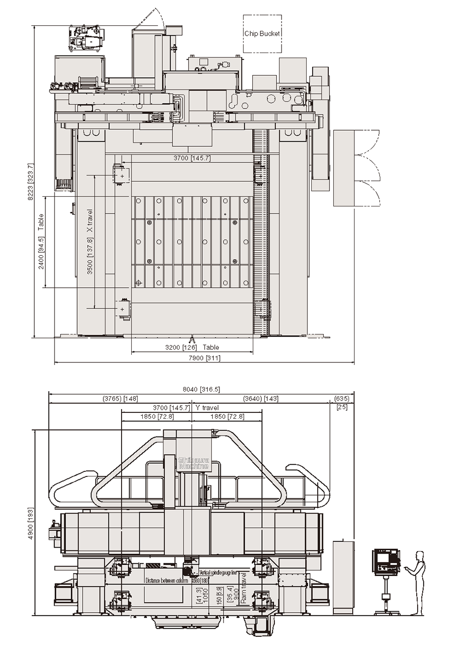
Machining Area of 5-face cutter head
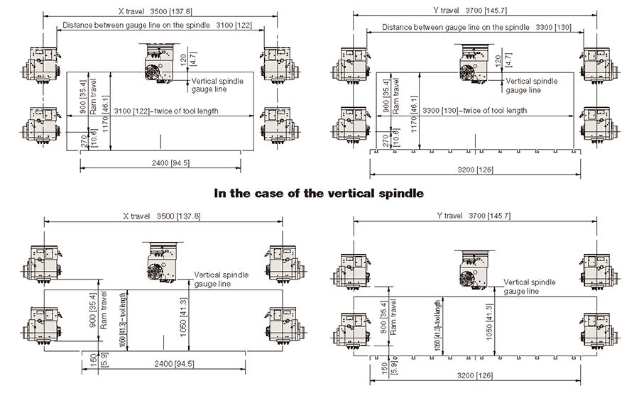
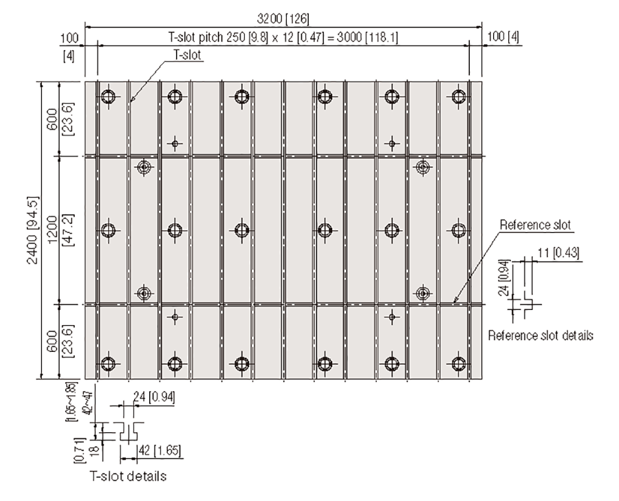
Table dimensions and slot layout
Optional Accessories Detail

Coolant unit (Item 13)
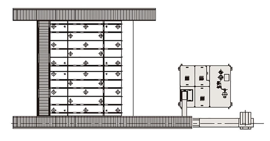
Chip Conveyor Layout (Item 10-A)
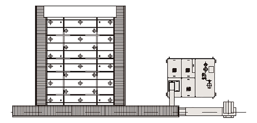
Chip Conveyor Layout (Item 10-B)
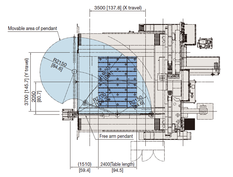
Free arm pendant (Item 24)
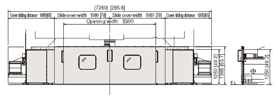
Front Chip Cover (Item 33)
Attachments
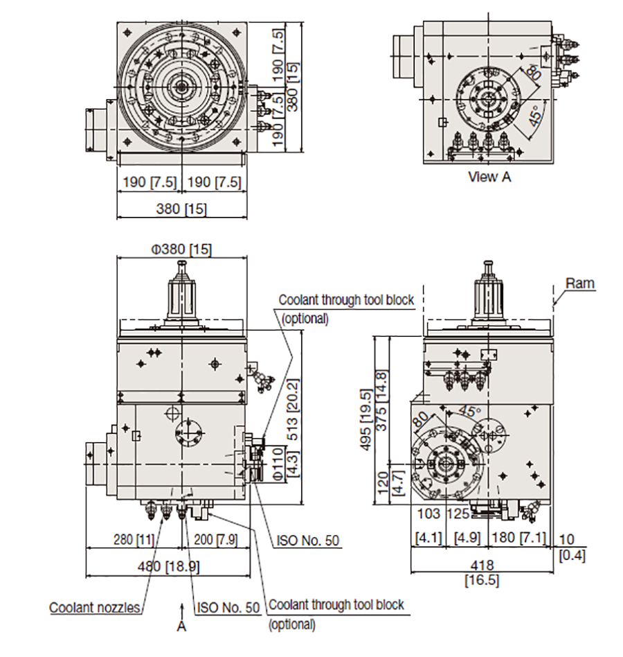
5-Face Cutter Head (standard accessories)
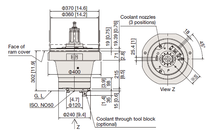
Snout 240 (optional accessories 9)
![0.07 Angle Head (30kW [40hp]/430min-1)](/images/en/product/machinetool/lineup/M/4624/MCW-4624_10-7.png)
0.07 Angle Head (30kW [40hp]/430min-1)(optional accessories 9)
